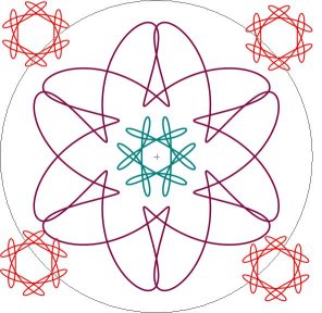
At any time one can press the button which is a red circle with 'Max' in it. This will make a circle for you which is the maximum possible size for the drawing window. The program was deliberately designed for an 800x600 size screen to max a maximum sized circle of 575.
One
can press the Esc key to toggle the size of the Drawing area back and
forth to the whole physical computer screen. When in full screen some
operations are still available using the hot keys. The way to hide the
application to the task bar is to click on the minimize square of the
Parameters title bar. The way to end the application is to click on the
X in the Parameters title bar, since the Paper section shown here does
not have that.

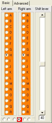
Each of the arms has a letter from A through R, and the
shift lever goes from 10 to 70. The computer program starts by
specifying the design of 60CC, which is a 6 sided clover.
A good thing to do to start is to copy the designs in the toy
instructions. Most of these designs are specified in a similar manner.
- Left arm is on left stud and right arm is on left gear.
- Left arm is on left stud and right arm is on right gear.
- Left arm is on left stud and right arm is on right stud. This is how one draws a permanent circle. Do not confuse this with the paper emulation where there is a temporary circle.
- Left arm is on left gear and right arm is on right gear. This is the default and almost all of the time you will use this setting.
- Left arm is on left gear and right arm is on right stud.
- Left arm is on right gear and right arm is on right stud.
These options are mutually exclusive and selected with the radio buttons from left to right. Some of these options are never used with the real toy, since the crank handle, which is used to turn the gears sometimes interferes with the arms. This is one of many "issues" which makes a computer different from a real life toy. See this and others in the Notes page.
With all circle stud options other than the red one, the values for advanced parameters are calculated, but the fields in the Advanced tab cannot be changed. Changing the circle stud also is like pressing the Default values button on the Advanced tab.